
SIGNUX PAN01
Power where the mains does not reach
Foldable solar kit with battery and pole bracket, to power field equipment where there is no mains supply. Three sizes, 12 V output, IP67 and status readout over RS485.
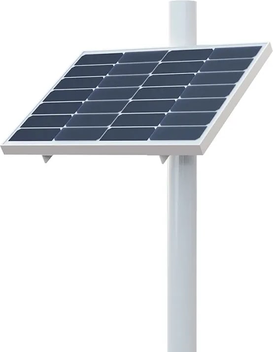
The PAN01 is a solar kit with a built-in battery, meant to power a piece of field equipment where the mains does not reach. It arrives as one assembly — panel, battery, electronics and bracket — and is unfolded and clamped to a pole.
The battery carries auxiliary heating that draws its current from the panel rather than from the reserve, so it works in the cold without spending autonomy on warming itself. The state of charge is worked out by an algorithm that recalibrates itself according to how the panel has been charging, and the whole unit is read over RS485.
It clamps to a vertical pole with two U bolts: no civil works, no trench and one person. When one kit does not cover the load, several can be put in parallel on the same equipment.
- Output voltage
- 9 to 12.6 V
- Maximum output current
- 10 A
- Protection
- IP67
- Operating
- −30 to 60 °C
What sets it apart
60, 80 or 100 W with 30, 40 or 50 Ah
Three sizes. Output of 9 to 12.6 V at 10 A, 90 % discharge depth, and 24, 36 or 48 V customised at 95 % efficiency.
−30 to 60 °C
Charges at −20 °C and discharges at −30 °C, keeping 95 % of its discharge in the cold thanks to the auxiliary heating.
IP67, and a panel for over 25 years
Class A monocrystalline at 21.6 % efficiency, on an SGCC galvanised steel and polycarbonate resin bracket.
Up to 8 kits in parallel
On the same equipment, when one alone does not cover the load. Status is read over RS485.
Configurations
| Power | Part number |
|---|---|
| 60 W | SX-PAN01-30 |
| 80 W | SX-PAN01-40 |
| 100 W | SX-PAN01-50 |
Specifications
General
- Type
- Solar kit with battery and bracket
- Output
- RS485Modbus RTU at 9600 and address 1. The register map is in the manual.
- Mounting
- On a vertical pole, 80 to 114 mmTwo U bolts, no civil works
- Expansion
- Up to 8 kits in parallelOn the same equipment
Solar panel
- Power
- 60 · 80 · 100 WDepending on the model
- Voltage
- 18 V
- Material
- Class A monocrystalline silicon
- Efficiency
- 21.6 %
- Service life
- Over 25 years
Battery and output
- Capacity
- 30 · 40 · 50 AhDepending on the model
- Operating voltage
- 9 to 12.4 V
- Output voltage
- 9 to 12.6 V
- Maximum output current
- 10 A
- Customised output voltage
- 24 · 36 · 48 VAt 95 % efficiency
- Discharge depth
- 90 %
- Output cable length
- 1.5 m
Operating conditions
- Operating temperature
- −30 to 60 °C
- Charging in the cold
- Down to −20 °C
- Discharging in the cold
- Down to −30 °CKeeps 95 % of its discharge
- Protection grade
- IP67
Construction
- Dimensions
- 580 × 480 × 70 · 765 × 480 × 70 · 765 × 630 × 70 mmDepending on the model
- Weight
- 6.5 · 10.5 · 11.5 kgDepending on the model
- Bracket material
- SGCC galvanised steel and polycarbonate resin
- In the box
- Kit with bracket, 2 U bolts, 2 fastening plates, DC cable, hex wrench, 6 M6 screws, 4 nuts, 4 washers, 4 spring washers and installation guide
Manual
1Introduction
The PAN01 powers a piece of field equipment where the mains does not reach. It is a closed assembly: solar panel, battery, charging electronics and folding bracket, all in one piece that is unfolded, clamped to a pole and working.
There are three sizes. They are chosen by the load of the equipment they will power and by how many days they have to last without sun.
| Model | PAN01-30 | PAN01-40 | PAN01-50 |
|---|---|---|---|
| Panel | 60 W / 18 V | 80 W / 18 V | 100 W / 18 V |
| Battery | 30 Ah | 40 Ah | 50 Ah |
| Dimensions | 580 × 480 × 70 mm | 765 × 480 × 70 mm | 765 × 630 × 70 mm |
| Weight | 6.5 kg | 10.5 kg | 11.5 kg |
The rest is common to all three: output of 9 to 12.6 V at up to 10 A, 90 % discharge depth, service from −30 to 60 °C, IP67 protection, a 1.5 m output cable and status readout over RS485.
2What comes in the box
- •Solar kit with its bracket
- •Two U bolts
- •Two bracket fastening plates
- •One DC cable
- •One hex wrench
- •Six M6 screws
- •Four nuts, four washers and four spring washers
- •One installation guide
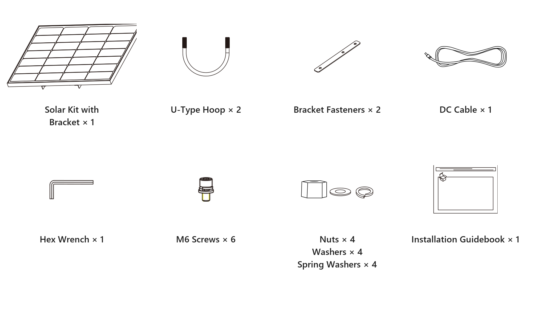
The box does not include the spanner for the U bolt nuts: they are M10 and take a 17 mm spanner. The hex wrench that is included is only for the M6 screws of the fastening plates.
3Mounting
One person can do the mounting and it needs no civil works: no trench, no buried cable, nothing to switch off. A vertical pole 80 to 114 mm in diameter is required, along with a 17 mm spanner and zip ties to gather the spare cable.
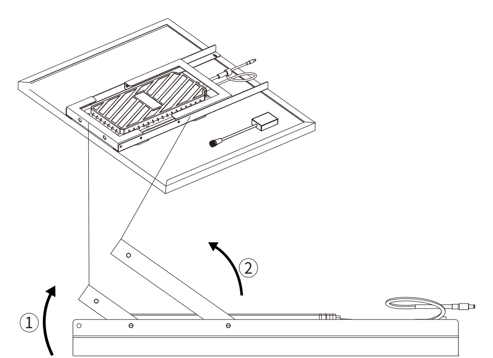
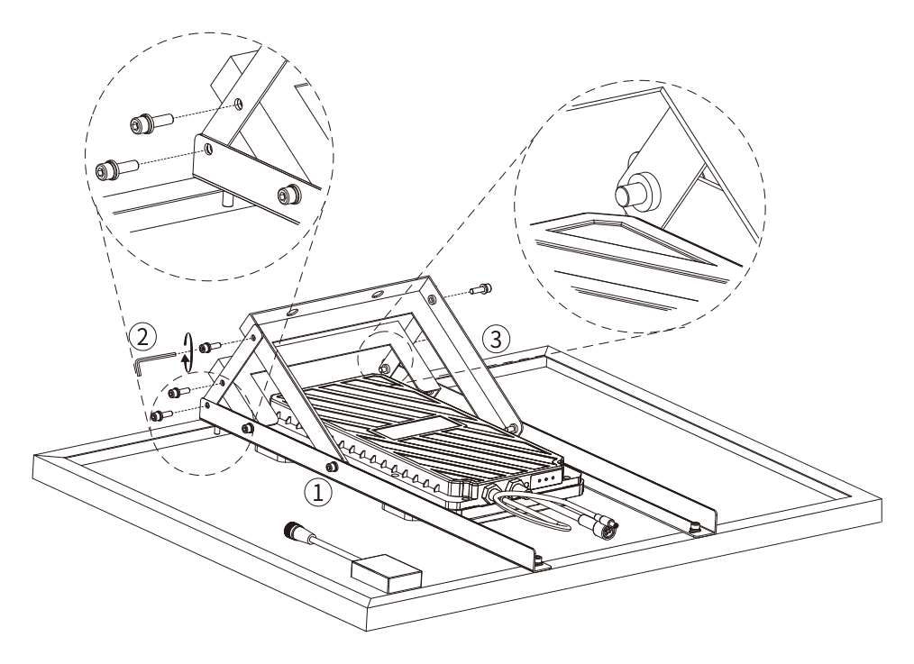
It takes seven steps, and the order matters: the bracket is assembled with the kit lying flat, not once it is up on the pole. The circled numbers in the drawings — ①, ②, ③ — mark movements, not parts.
3.1Laying the kit flat
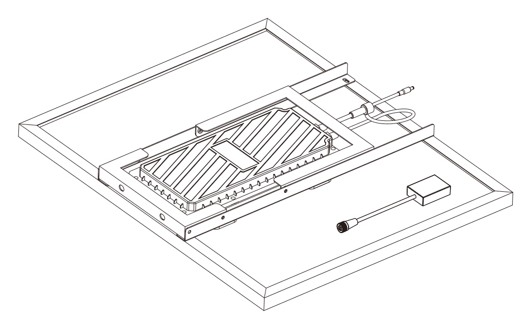
Lay the kit flat and face down, with the panel against the ground and the folded bracket in view, on a flat and clean surface. It is advisable to put the box itself or a blanket underneath, because the panel will be resting on its good face and any grit will scratch it.
Before going on, check that the output cable is clear and that it will not be trapped between the bracket and the frame when unfolding.
3.2Unfolding the bracket
The bracket opens in two movements, in this order:
- •① Lift the anchor frame by pulling it upwards: it turns on the hinge along the lower edge.
- •② Swing the triangular arm outwards until it stops.
3.3Fastening the plates
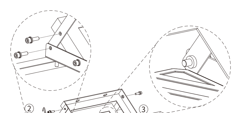
The two plates are what make the bracket rigid: until they are in place, the arm folds back on its own. One goes on each side.
- •Line up the holes at the top of the plate with the inner holes of the bracket arm.
- •Put in the six M6 screws.
- •Tighten with the supplied hex wrench.
- •Repeat on the opposite side and check that both arms are left at the same angle.
3.4Connecting the panel to the battery
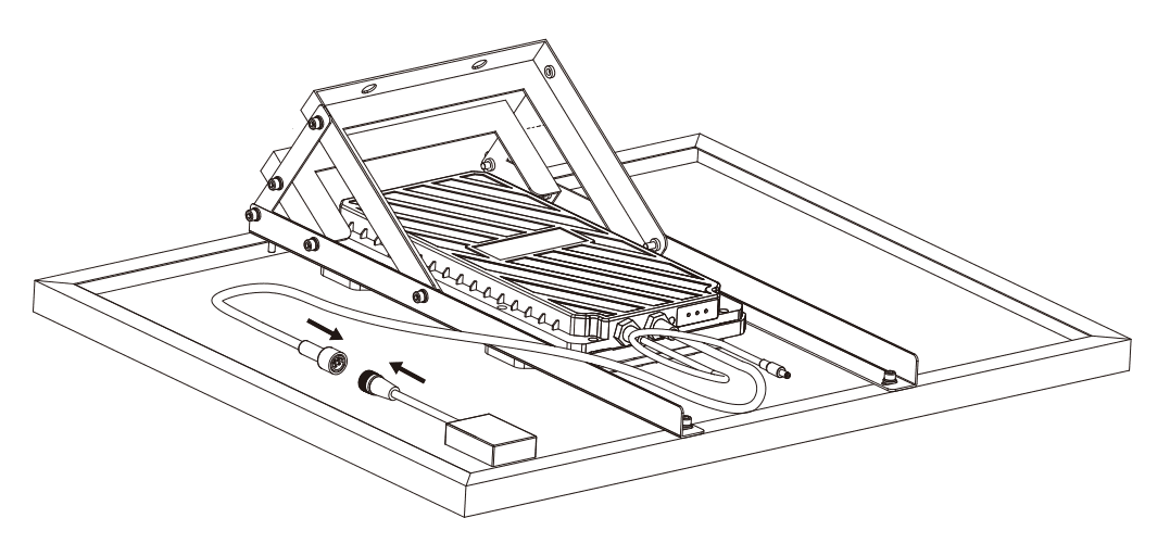
Panel and battery are joined by a sealed connector that cannot be got wrong: it has an orientation key and goes in one way only. Do not force it if it will not go in; turn it until the key lines up.
Screw the outer collar fully home. That is what compresses the seal and what keeps the IP67: half screwed in, the joint is not sealed even though it makes contact.
3.5Clamping to the pole
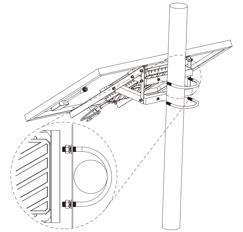
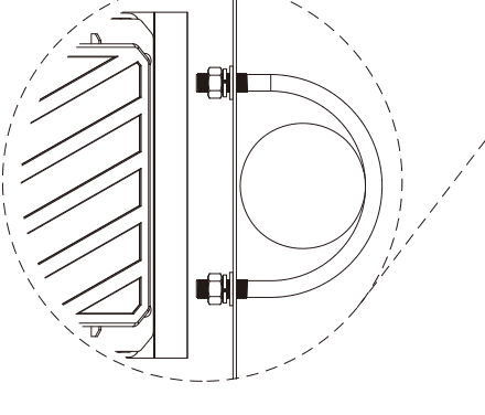
With the bracket assembled, lift the unit onto the pole. It takes tubes 80 to 114 mm in diameter.
- •Wrap the tube with the two U bolts.
- •Put the threaded ends through the holes in the bracket plate.
- •On each stud, in this order: flat washer, spring washer and M10 nut.
- •Tighten the four nuts with the 17 mm spanner.
It is advisable to tighten crosswise and gradually, giving each nut one turn in sequence. If one is tightened fully before the others, the bracket ends up skewed on the tube and there is then no way to straighten it.
3.6Mounting finished, and orientation
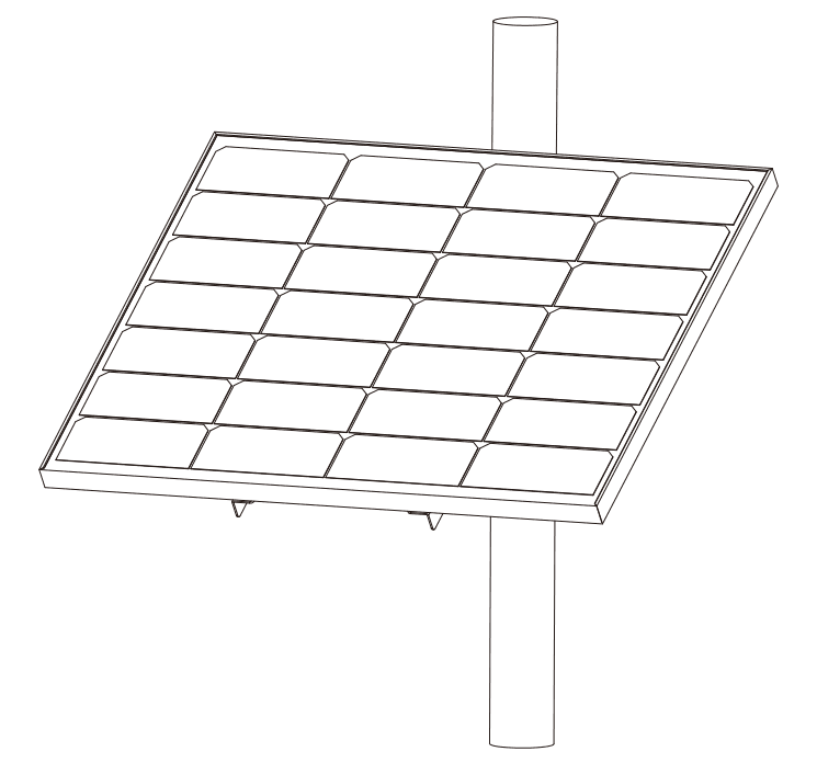
This is where the mechanical mounting ends. Before the final tightening, turn the unit on the pole and leave it facing the right way.
The same as for any other photovoltaic installation: facing the midday sun and with no shade over it at any time of day — not from trees, not from a building, and not from the mast itself if something is mounted higher up. A shadow crossing the panel for a few hours a day costs far more autonomy than it looks.
3.7Connecting the equipment and dressing the cable
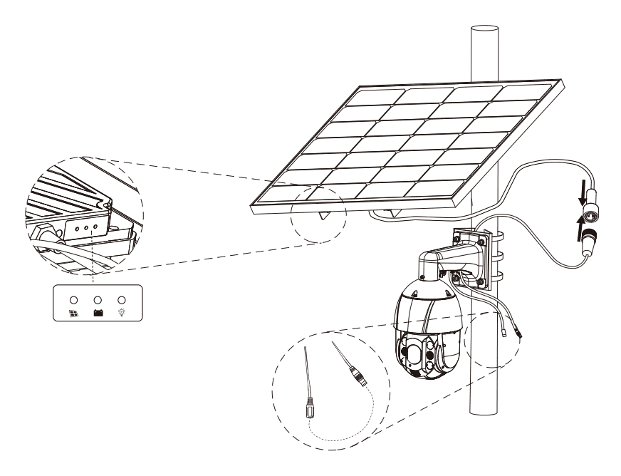
Fix the equipment to be powered to the same pole, below the kit, and connect it to the DC output cable, which is 1.5 m long.
If there is spare cable, gather it with zip ties against the mast rather than leaving it hanging: a loose cable in the wind eventually breaks at the gland, and that is a fault nobody sees until the equipment loses its supply.
With everything connected, look at the three indicator lights. What each one says is in the next section.
If one kit does not cover the load, several can be put in parallel on the same equipment, up to eight.
4The indicator lights
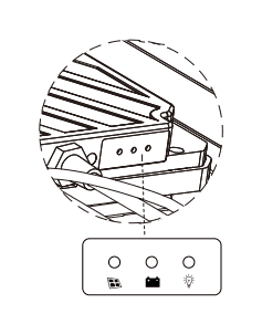
The unit carries three indicator lights together, under the panel. They say, in this order, whether the panel is charging, how the battery is, and whether output is available.
| Light | Colour | What it means |
|---|---|---|
| Solar panel | Green | On: the panel is charging · Off: the panel is not charging |
| Battery | Green | On: the battery is normal · Flashing slowly: battery low · Flashing quickly: battery exhausted |
| Load | Red | On: output is available, which does not mean it is being drawn · Off: output is not available |
5Reading the unit over RS485
The unit speaks Modbus RTU over RS485. Reading it tells you live what comes in from the panel, what goes out to the load, how the battery is doing and what voltage each cell is at.
The measurement areas are read with function 04, and the counter and parameter areas with 03. The unit also lets the parameter areas be written.
5.1How to talk to it
| Setting | Value |
|---|---|
| Protocol | Modbus RTU |
| Speed | 9600 bps |
| Format | 8 data bits, no parity, 1 stop bit |
| Factory address | 1 |
| Function | 04 for the measurements · 03 for the counters |
| Reply | Under half a second |
The measurements live from 0x0200 to 0x0221 and in the 0x0300 block; the cumulative counters, in the 0x0400 area.
Two things are worth knowing before programming anything. First: if you ask for more registers than the block holds, the unit returns the ones it has and says nothing — asking for forty from 0x0200 returns thirty-four. Second: past 0x0303 the cell block returns leftover memory that looks like data and is not.
If it answers nothing at all, before doubting the baud rate it is worth swapping the A and B wires.
5.2What can be read
| Register | What it is | Scale | Unit |
|---|---|---|---|
| 0x0200 | Control information | bit field | — |
| 0x0201 | Alarm message | bit field | — |
| 0x0202 | Alarm message | bit field | — |
| 0x0203 | Remaining capacity | ÷ 10 | Ah |
| 0x0204 | Charge (SOC) and PWM duty | one byte each | % |
| 0x0205 | Battery power | no scale | W |
| 0x0206 | Battery total voltage | ÷ 10 | V |
| 0x0207 | Battery total current | ÷ 10 | A |
| 0x0208 | Battery charging current, photovoltaic side | ÷ 100 | A |
| 0x0209 | Discharge current, load side | ÷ 100 | A |
| 0x020A | Temperatures 1 and 2 | one signed byte each | °C |
| 0x020B | Temperatures 3 and 4 | one signed byte each | °C |
| 0x020C | Temperatures 5 and 6 | one signed byte each | °C |
| 0x020D | Temperatures 7 and 8 | one signed byte each | °C |
| 0x020E | Temperatures 9 and 10 | one signed byte each | °C |
| 0x020F | Temperatures 11 and 12 | one signed byte each | °C |
| 0x0210 | Temperatures 13 and 14 | one signed byte each | °C |
| 0x0211 | Temperatures 15 and 16 | one signed byte each | °C |
| 0x0212 | Clamp voltage of the discharge protection | ÷ 10 | V |
| 0x0213 and 0x0214 | Internal timestamp, 32 bits | no scale | s UTC |
| 0x0215 | Days remaining | no scale | days |
| 0x0216 | Health (SOH) and PWM duty | one byte each | % |
| 0x0217 | Photovoltaic voltage | ÷ 10 | V |
| 0x0218 | Photovoltaic current | ÷ 100 | A |
| 0x0219 | Mains current | ÷ 100 | A |
| 0x021A to 0x021E | Reserved | — | — |
| 0x021F | Temperature protection, charging and discharging | one byte each | — |
| 0x0220 and 0x0221 | Reserved | — | — |
The signs: in 0x0207 and 0x0209 discharge is positive and charging negative; in 0x0208 and 0x0218 photovoltaic discharge is positive, and in 0x0219 it is the mains discharge.
The sixteen temperatures go in pairs, one signed byte each, from −50 to 125 °C. A channel with no sensor fitted reads −50.
The timestamp in 0x0213 and 0x0214 is a 32-bit integer in UTC seconds: the first is the high half and the second the low half.
In 0x021F the value 0 is normal. The highest bit marks temperature protection, the next marks discharge protection and the lowest, charging protection; each number from 0 to 127 identifies a cause.
5.3Extended cells and probes
Cells and temperature probes have their own areas. The origin documents them as ranges, because how many there are depends on the unit: the last address to read is worked out from the count given by the first register of each area.
| Register | What it is | Scale | Unit |
|---|---|---|---|
| 0x0300 | Number of cells | no scale | — |
| 0x0301 to 0x03FF | Voltage of cells 1 to 255 | ÷ 10000 | V |
When the number of cells exceeds what fits in one reply, they are asked for in several packets. Cells above 255 are in the 0x07xx area.
| Register | What it is | Scale | Unit |
|---|---|---|---|
| 0x0280 | Number of temperature probes | no scale | — |
| 0x0281 to 0x02FF | Temperatures 1 to 254, in pairs | one signed byte each | °C |
The probes from 0x020A to 0x0211 are the board ones. In this area, as there, the range is −50 to 125 °C and a probe that is not fitted reads −50.
| Register | What it is | Scale | Unit |
|---|---|---|---|
| 0x0700 to 0x07FF | Voltage of cells 256 to 511 | ÷ 10000 | V |
This area is only used when the total number of cells exceeds 255.
5.4Counters and miscellaneous parameters
The 0x04xx area is read with function 03. It gathers the battery totals, the energy counters, the rental clock and the encoding registers.
| Register | What it is | Scale | Unit |
|---|---|---|---|
| 0x0400 and 0x0401 | Internal battery timestamp, 32 bits | no scale | s |
| 0x0402 and 0x0403 | Rental start timestamp, 32 bits | no scale | s |
| 0x0404 | Rental days | no scale | days |
| 0x0405 and 0x0406 | Cumulative discharge Ah, 32 bits | ÷ 100 | Ah |
| 0x0407 and 0x0408 | Ah value calibration, 32 bits | ÷ 10 | Ah |
| 0x0409 and 0x040A | Remaining capacity, 32 bits | × 2 | mAs |
| 0x040B to 0x040D | Registered phone number, 48 bits | no scale | — |
| 0x040E and 0x040F | Cumulative charge Ah, 32 bits | ÷ 100 | Ah |
| 0x0410 to 0x041C | Encoding registers 1 to 13 | one byte each | — |
| 0x041D and 0x041E | Photovoltaic generation of the day, 32 bits | no scale | Wh |
| 0x041F and 0x0420 | Cumulative photovoltaic generation, 32 bits | no scale | Wh |
| 0x0421 and 0x0422 | Consumption of the day, 32 bits | no scale | Wh |
| 0x0423 and 0x0424 | Cumulative consumption, 32 bits | no scale | Wh |
| 0x0425 | Forced charge and discharge switch | bit field | — |
| 0x0426 | Reserved and protocol version | one byte each | — |
All 32-bit values go in pairs and in network order: the first register is the high half and the second the low half.
Rental days accept 0 to 3000. The thirteen encoding registers hold 26 bytes, two per register.
The four energy counters are updated once a day, at 00:00: the daily one holds the previous day and the cumulative one everything before that cut.
In 0x0425, the value 1 is automatic and 0 is forced shutdown.
5.5General parameters
The 0x08xx area holds the battery management system parameters: protection thresholds, calibrations and identity data. They are read with function 03.
| Register | What it is | Scale | Unit |
|---|---|---|---|
| 0x0800 | Discharge overcurrent, level 1 | ÷ 100 | A |
| 0x0801 | Level 1 delay | ÷ 5 | s |
| 0x0802 | Discharge overcurrent, level 2 | ÷ 100 | A |
| 0x0803 | Level 2 delay | ÷ 5 | s |
| 0x0804 | Cell overvoltage | ÷ 10000 | V |
| 0x0805 | Cell over-discharge recovery | ÷ 10000 | V |
| 0x0806 | Cell overcharge recovery | ÷ 10000 | V |
| 0x0807 | Cell charge voltage | ÷ 10000 | V |
| 0x0808 | Battery: heat alarm and protection | one signed byte each | °C |
| 0x0809 | System: heat alarm and protection | one signed byte each | °C |
| 0x080A | Number of cells | no scale | — |
| 0x080B | Rated capacity | no scale | Ah |
| 0x080C | Current range | no scale | A |
| 0x080D | Current zero offset | ÷ 100 | A |
| 0x080E | Voltage calibration and charge current zero offset | one byte each | — |
| 0x080F | Current false alarm threshold | ÷ 100 | A |
| 0x0810 | Overcurrent threshold | ÷ 100 | A |
| 0x0811 | Full cell voltage | ÷ 10000 | V |
| 0x0812 | Cell float voltage | ÷ 10000 | V |
| 0x0813 | Equalisation turn-on voltage | ÷ 10000 | V |
| 0x0814 | Low temperature protection, charging and discharging | one signed byte each | °C |
| 0x0815 | Heating: turn-on and turn-off | one signed byte each | °C |
| 0x0816 | Low temperature recovery, charging and discharging | one signed byte each | °C |
| 0x0817 | Temperature probe enable | bit field | — |
| 0x0818 | Program function switches | bit field | — |
| 0x0819 | Segment voltage for the differential alarm | ÷ 10000 | V |
| 0x081A | High differential alarm | ÷ 10000 | V |
| 0x081B | Low differential alarm | ÷ 10000 | V |
| 0x081C | Mains switching voltage | ÷ 10000 | V |
| 0x081D | High voltage differential alarm | ÷ 10000 | V |
| 0x081E to 0x0820 | Device identifier, 48 bits | no scale | — |
| 0x0821 | Total undervoltage protection | ÷ 10 | V |
| 0x0822 | Total overvoltage protection | ÷ 10 | V |
| 0x0823 | Probe enable and discharge heat protection | one byte each | — |
| 0x0824 | Overcharge recovery SOC and mains current offset | one byte each | — |
| 0x0825 | Low voltage differential alarm | ÷ 10000 | V |
| 0x0826 | Mains and load current range | one byte each | — |
Temperatures in this area go as everywhere else in the unit: two signed bytes in one register, from −50 to 106 °C.
The ranges each parameter accepts: 1.00 to 655.00 A for currents, 1.5000 to 4.4000 V for cell voltages, 2.0 to 2000.0 V for total voltages and 1.0 to 100.0 s for delays.
The device identifier is 48 bits across three registers, meant to carry a MAC address.
5.6Master-slave control
The 0x089x area configures the up to thirty-two chained controls. It is read with function 03.
| Register | What it is | Scale | Unit |
|---|---|---|---|
| 0x0890 | Serial control number | one byte each | — |
| 0x0891 to 0x08B0 | Control 1 to 32: enabled probes and number of cells | four groups of 4 bits | — |
In each register, the eight high bits enable probes 1 to 8, from lowest to highest. Of the eight low bits, the upper four give the number of cells of the first sampling block and the lower four, that of the second.
5.7Factory information
The 0x06xx area is factory data. The origin documents it like this:
| Register | What it is | Scale | Unit |
|---|---|---|---|
| 0x0600 to 0x0607 | Internal use, not implemented | — | — |
| 0x0608 | Modbus address, parity and baud rate | one byte each | — |
In 0x0608 the high byte is the address, from 1 to 247. Of the low bits, two give the parity — 0 none, 1 odd, 2 even — and the remaining six the baud rate in multiples of 2400 bps: a 4 is 9600. The change does not take effect until the unit is restarted.
5.8The bit fields
Four registers are not a number but one bit per thing. The origin breaks them down like this.
| Bit | What it says when it is 1 |
|---|---|
| 2 | Heating on |
| 3 | Heat dissipation on |
| 4 | Buzzer silent |
| 5 | Heat protection triggered |
| 6 | Discharge enabled |
| 7 | Charging enabled |
| 10 | Mains charging enabled |
| 11 | Mains connected |
| 0, 1, 8 and 9 | Reserved |
In 0x0200 the normal value is 0x00D0.
| Bit | What it says when it is 1 |
|---|---|
| 0 | Heat protection: the protection threshold has been passed |
| 1 | Severe overcurrent: the level 2 threshold has been passed |
| 2 | Charging overcurrent |
| 3 | Overcharge: a cell above the overcharge voltage |
| 4 | Battery exhausted: a cell below the over-discharge voltage |
| 5 | Heat alarm: the alarm threshold has been passed |
| 6 | Discharge overcurrent: the level 1 threshold has been passed |
| 7 | Battery low: a cell below the recovery voltage |
| 8 | Difference between cells above the threshold |
| 9 | Cold while charging: below the low temperature protection |
| 10 | Cold while discharging: below the low temperature protection |
| 11 | Charging voltage difference too high |
| 12 | Short circuit |
| 13 | Humidity above the alarm threshold |
| 14 | Insulation measurement alarm |
| 15 | Charger not compatible |
In 0x0201 the normal value is 0x0000: with the battery in order, not one bit.
The 0x0202 is not a bit field but two bytes: the high one is the fault code and the low one its level, from 1 to 3, where 3 is the most serious. A code of 0 is "no fault". If several coincide, only the most serious is reported.
| Bit | What it does | Default |
|---|---|---|
| 0 | Priority: 0 the battery, 1 the mains | 0 |
| 1 | Data sending: 1 on its own initiative, 0 when the master asks | 1 |
| 2 and 6 | Cell type, with 6 as the high bit: 0 lithium iron, 1 ternary, 2 Xingying ternary | 1 and 0 |
| 11 | Short circuit protection | 0 |
| 3 to 5, 7 to 10 and 12 to 15 | Reserved | 0 |
In 0x0818 the default value is 0x07.
5.9Knowing what is going on
Which way the current is flowing cannot be worked out from which register reads zero: panel current and load current are measured separately and can both be non-zero at once. What tells you is the sign of the net battery current.
- •0x0207 positive: the battery is discharging.
- •0x0207 negative: the battery is charging.
- •And always, 0x0207 is the load current minus the panel current.
The power in 0x0205 is the battery power, not the panel power: it is the absolute net current times the voltage, in whole watts. The power the panel delivers has no register of its own and is worked out by multiplying 0x0217 by 0x0218.
The cycles the battery has done come from the cumulative charge Ah divided by the nominal capacity of the model.
6Writing parameters
The parameters in the 0x04xx, 0x06xx and 0x08xx areas can be written, but they are not usage settings: they are the thresholds the management system protects the battery with. A wrong write moves a safety threshold, the unit accepts it without warning and there is no comfortable way back.
Gallery
Documentation
Does it fit your case?
Tell us where the SX-PAN01 is going and what you need to integrate it with. We’ll tell you whether it’s the right device — and if not, which one is.